
Suppose a healthy young adult finds a summer job, working on a construction site. And that he or she is employed by an individual or carpentry firm that is currently building houses, condominiums or some other wood framed building. Eventually the stage of construction will pass the first story, or perhaps a second or third story before arriving at the roof level. Suddenly all the saw cuts on boards will change from being simple square cuts, to becoming unfamiliar angled cuts or even complicated compound cuts (where the saw blade is first set at an angle, before cutting the board on a diagonal line too).
This young student, apprentice or temporary laborer might still be in high school, a college dropout or a doctorate of sociology; but the point is that they should have had some math. Enough math probably that when they see so many angles and triangles, that they may attempt to jump right in with the troublesome expectation that their knowledge of geometry and trigonometry will be crucial, or accurate. It won’t be. While education is certainly important even when building; it can also sometimes get in the way. In the real world, builders and fabricators do things differently and they take shortcuts. The student’s education therefore, will be continuing anew on the job site.
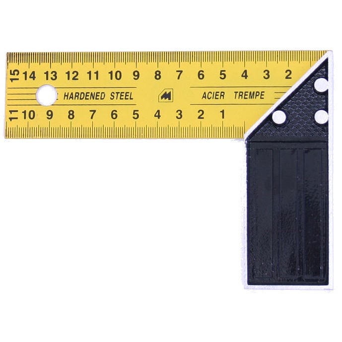
The “featured image” above displays an innovative tool known as a “speed square” and a diagram of 12 common roof pitches. But there are much steeper roof pitches not shown, which are seldom used in modern buildings. A “24:12 pitch” or “full pitch” for example would be straight up and down.

Pitch & Slope
Most people could go through their entire lives without making a distinction between “pitch” and “slope”. Even people in the building trade, for the most part assume that the two terms are synonymous. In books, on blueprints or on YouTube videos which purport to be educational; people are still getting it wrong today. Its not a crucial issue, but one that could lead to misunderstandings and errors. Pitch is an older term than slope, and it is a reference which uses the entire span of a roof; not just half the span. Pitch is expressed as a fraction that can be reduced, whereas slope is a ratio traditionally fixed as an expression in ‘inches per foot’. This guy explains the discrepancy well.
The tool in the beginning featured image took the world of carpentry by storm in the 1970s (at least in America and Canada where timber framing is common). The first “Speed Square”®, and the best one still, was invented by Albert Swanson back in the 1920s. It took 50 years to become a widely recognizable and commonplace tool. The carpentry tools that speed squares frequently replaced in construction were the “tri square”, “combination square” and sometimes even the venerable “framing square”. Swanson’s patent eventually expired though, and now the market is thoroughly awash with copycat versions of the original tool. It was not the triangular shape of the speed square that made it innovative, but its markings. Almost all building squares can be used to check or mark square cuts, but not the angled cuts. The “degrees scale” on the square is useful in its own right, but protractors had already existed before. Albert Swanson’s real innovation was in the refinement of a simple “one number strategy”, where when given the pitch (slope rather) – that a single integer between 1 and 10 (usually) would be the only number a carpenter would use on the scale – to initiate all the cuts on a given roof. (Unless it’s a building with an uneven roof pitch, which means two or more pitches in the same roof).

Beyond the common rafters of a roof (each with top cut, bird’s mouth and tail to consider) there might also be hips, valleys, hip and valley jack rafters, cripple jack rafters, dormer rafters, gable studs and collar ties to cut. Each cut unique. It’s up to the carpenter to understand the differences and to calculate the differing cuts and lengths in these boards. Things can get complicated. The elegance of the speed square tool is that once the roof slope was specified or known (assume a 6:12 for example) then all cuts in the roof could be initiated correctly. By holding the square on one number (6) to scribe a cut mark to the board, whether using either the hip & valley or common scales where appropriate. The tool also came with a small booklet of simplified data, used to calculate rafter lengths.

Until recently all speed squares had been beholden to the ‘foot and inch’ of the Imperial measurement system. Now there are metric versions however. Historically Swanson’s “one number method” for layout and marking rafters, used a ratio where the rise could vary but the run was understood to remain a constant 12 inches. The hip and valley ratios though (where the theoretical hypotenuse of the run is longer and offset at 45°) differ by using 17 inches for the run instead of 12”. And almost a century later now Swanson seems to be the first company to adapt its speed square to the metric system. The degree scales between the Imperial and metric versions of the square are identical. At first glance the common and hip & valley scales seem to be identical too, but they are not. On metric speed squares, ratios are based on scales calculated by using (10) decimeters for the common run, and (14) decimeters for the hip & valley run.


The most common roof styles on houses are butterfly, gable, gambrel, hip, mansard and shed shaped roofs. Although attractive, practical and efficient with materials; the hip style roof was once the most common style, but now is rare. The hip styled roof also demands the most skill to cut. Most carpenters working today have never built one either. The reason is that back in the 1950s, someone invented the wooden roof truss. Seventy -five percent of the roofs constructed today use prefabricated roof trusses. Its much easier to have a truckload of trusses delivered; than to measure, cut, and fasten together by hand – each and every board that goes into a roof. But also, the modern roof truss usually represents a more cost-effective and structurally superior method of construction in the long run. Although truss companies can mimic the outward appearance of a hip styled roof, it is cheaper and more commonplace for developers to crank out buildings which feature less aesthetic, gable style roofs instead.

X marks the girder -truss, which here is comprised of 2 trusses with strong cords nailed together; to carry the weight of the common trusses hanging from it.
Before WWII most carpenters still used only handsaws, chisels, block planes, eggbeater drills and bit braces. Although hand held electrical circular saws were being invented and were going through the patent process in the 1920s these tools didn’t catch on or become commonplace until after the Depression and the following War, were over. Even into the 1970s, most carpenters didn’t consider themselves properly equipped unless they carried a couple of handsaws to the job. Hand saws today have largely been replaced by the reciprocating saw. Milwaukee Tool produced the first Sawsall. The first electrical circular saw was a “worm drive” produced by the Electric Hand Saw Co. – which later became the Skilsaw Inc. company. The so-called “sidewinder” or direct drive circular saw was invented by Porter-Cable a little later in the 1920s, to circumvent the Skilsaw patent.

‘There is more than one way to skin a cat’ * <see footnote #3>
Getting back to the beginning “featured image”: the “speed square” was not the first tool or scribing square to cause excitement in the microcosm of American construction. The “carpenter’s framing square” was. Two centuries ago. Then a century later the idea of stamping onto that square, the pre-calculated tables for just ¼ pitch, 1/3 pitch and ½ pitch common rafters proved to be sensationally novel. Builder’s squares of some type have probably existed since before the Pyramids were built. Right angle squares made of wood had existed a long time before 1817 which was the year in which a blacksmith received his patent for inventing the first all metal “framing square”. He had refined his idea from before where he had (over a blacksmith’s forge) welded two steel rock cutting saw-blades together at a right angle. At first, metal framing squares had no markings but later accurate increments in inches were scored along both edges of the tongue (16” long x 1 ½ wide) and the blade (24” long and 2” wide).

As with the later speed square, over the years a multitude of companies would copycat the first framing square; after the original patent ran out. There was a definite need or impetus for builders to find an easier and quicker way to calculate roof cuts. At the turn of the last century several companies were seeking patents just for the useful rafter length tables they were stamping into the center-space of their own tool. When given a known roof pitch and span between walls, such tables were used to draw or tabulate the common rafter top cut, the common rafter lengths, the side cut of the hip or valley, the length of hip and valley rafters, the side cuts for the hip or valley jack rafters and the lengths of those same jack rafters for either 16” or 24” spacing. Some steel squares were even stamped with a scale for octagons and / or decimal tables converting 100ths part of a foot, into inches.

On large construction sites with large work crews, it was (and still is) knowledge that “separates the men from the boys”. In the past it was the worker that taught himself in his spare time, the tricks of using a framing square effectively, who might be promoted to foreman. The others, without that effort to educate themselves, were destined to sweat at more menial labor. The framing square is too large to carry around on your belt or in your nail pouch though, and size is one reason why the speed square replaced the framing square in several roles. There is not enough room to stamp rafter tables onto a standard speed square however. The Swanson Speed Square came with a concise, pocket sized booklet with illustrations, explanations and those important rafter tables.

One place where the 200 year old framing square still outshines any other tool and has no superior modern replacement, is when cutting stair jacks (or runners or stringers). Given any random distance between levels, a builder must ensure that the measurement of each step on a stairway between start and finish, should be as close to as identical as possible. There are building code limits detailing how tall a step can be (7 ¾” max) and how wide a stair tread can be (10” min). There are many other important details germane to building stairs, which will be dismissed for now. Just understand though that the task is not simple and that the antique framing square is still the best tool for the job. In practice a strong wide board like a 2”x10” or 2”x12” would be placed on some sawhorses and then the units for rise & run would be measured and marked before sliding the framing square up or down the board to the next step. This “stepping off ” as it is called would have been used to calculate and cut roof rafters also, if using a framing square which had only ruled edges (no rafter tables).

The proportionality of ‘slope’ works regardless of the unit of measurement used. If the units of measurement were uniform petrified pterodactyl eggs, then roof slope would be calculated as the ratio of : (rise in pterodactyl eggs / run in pterodactyl eggs). For historic (or standard) framing squares and speed squares which use the Imperial “inch per foot” method for pitch (slope), the scale and measurement is based on 12 because there are 12 inches in a foot. The metric scale presents no complication to the concept of slope. Here, slope is understood to be a rise in centimeters over a fixed unit of 10 centimeters for the run. Metric roof slopes are expressed in degrees. A builder says “18° slope” instead of “4:12 slope” although the two are essentially the same. For a construction calculator or square marked in metric, the hip and valley cuts would be calculated by using a ratio in centimeters over a run of 14 cm.

One company purportedly acquired a design patent in 2011 for the modifications it made and the scales that it stamps into the already ubiquitous framing square. <see footnote #1> The stamping on this square claims to be universally applicable to both standard and metric units of measurement (and to provide tables shared by both units – without the need to make conversions). The ‘Chappell Universal Square’ achieves this by decimalizing the inch. Not into just 10 parts (which is hardly a new idea) but into 20 parts. Then each 1/20th mark on the scale becomes .05 inches. Then the ¼ inch mark on a standard scale becomes .25 inches, 1/2” becomes .5” and 3/4” becomes .75 inches. Although the metric scale is not etched into the metal of the blade, the metric user can still easily count units and still use all the rafter tables without needing to convert or make sense out of the imperial units of fractional inches. Besides the speed square (in metric), no one else seems to have made an effort to manufacture a physical tool which caters to the needs of a roof builder using metric. Today’s professional roof builder using metric probably depends upon high-tech calculators and trigonometry. Making the builder resort to trigonometry is what those old Imperial metal carpentry squares tried to avoid.
A very useful source of information concerning framing squares is provided by <this link>.
From that link just provided, was a book published in 1908 named: A Framing Guide and Steel Square, A Practical Treatise (by Dallas Sigmon). Like many other books of that century it had a preamble that encouraged good work ethics and personal ambition. The book contains procedural explanations, charts, general information and auxiliary data. The book also explains how to use the framing square as if it were some forerunner of a slide rule or an electronic calculator. <footnote #2> Simon describes a few ingenious methods to do quick and simple multiplication and division with the framing square. He does not pause to explain why his methods work though, which can be aggravating. But perhaps his teaching method better equips the reader in the long run somehow – for them having to work out the logic for themselves.
Examples: He ask questions like:
“If cloth were 5½ cents per yard, how much would 4½ yards be worth”? And then he explains how to find the answer on the square.
Later Sigmon ask: “If lumber were $24.00 feet per thousand, what would be the cost of 750 feet”? Then he explains what edges of the square to use, what numbers to hold, hypotenuse to draw or scale to use before coming up with the answer “$18.00”.
(Did you notice that price ? Those units are in “board feet” (1” x 1” x 12”) and one thousand board feet makes a fairly good sized bundle. In May 2021 lumber prices were hovering around $1,750.00 per thousand board feet. $1,750.00 is 7291.667 percent of $24 and that is what some people call inflation).

One of the very few illustrations in Sigmon’s book, this one is used to explain how to determine the width of a river. The solution is compelling but is explained very tersely. His text does not tell how he uses his framing square to site his stakes, nor does he describe his “line”(string-line) well, or tell how he is using the square from that line to “square up” the smaller triangle. On the next page though, he better explains how to accurately judge the height of a tree, using similar techniques with a square.

As mentioned before, the hip roofs which were once very commonly constructed in the past, are rarely built today. The mainstream attention has gone to truss-roof construction. Many people that consider themselves carpenters today have in fact had absolutely no experience with roof hips or real rafters. The call for calculating rafter lengths and complicated compound cuts on jack rafters is much less crucial today than it once was. The need for tables differentiating between hexagon and octagon roof rafter cuts is even more rare; yet those tables are stamped into some framing squares.
“Time is money”. Time wasted calculating funky complicated angle cuts – is a loss of money if there is a simpler way to find a solution. Efficiently and expediency are ‘the name of the game’ in professional construction. Builders might be more-so a ‘product of their times’ than the rest of the populace. Once a new tool comes out, they all rush to get one. The framing square saw its heyday come and go. The speed square too is less significant than it once was. But builders still need those physical edges to scribe pencil lines onto boards and other stock, before cuts are made.
Today’s technology being what it is, a qualified builder probably carries a smartphone or a specialized construction calculator in his pocket. He may own a framing square and a speed square both, but probably does not stoop to understanding or using their old fashioned data tables. Naturally these new electronics can be considered to be the more powerful tools in the long run, for having multiple functions and more capability. The notion though that any such modern technology is easier, faster or more accurate to any degree of significance; is misguided. On a roof or on a staircase, if it were put to the test; it is highly doubtful that a modern carpenter using his calculator or phone, could even approach the mensuration productivity of an ancestor who was truly efficient in the use of one of these old squares.
The old bygone contractor in his effort to learn and to understand the tricks of his tool might have also taken more time in his consideration of trigonometric principles than his modern day counterpart does; whom can just punch a button and skip the contemplation. If a modern day contractor depends upon calculators or ‘apps’ to do this thinking for him, let’s hope he never drains his batteries, looses his Internet connection or drops and bust his electronic gadget from some high, partially finished roof.
———————————————————————————————————————–>
<footnote #1> * Basically there are two different kinds of patents. Utility patents – which protect functional aspects of an invention; last for 20 years before they expire, or sooner if fees are not payed. Design patents, which protect the aesthetics or appearance of an object last for 15 years and require no fees to maintain.
<footnote #2> * Slide rules allowed people like scientists, engineers, navigators, surveyors, astronomers and others – a method to preform computations quicker (multiplication, division, square roots, cube roots, sines, tangents, etc…… but not addition or subtraction). The logarithmic scale is useful for displaying numerical data over a very wide range of values. Although invented 400 years ago (about 1622) and just a few years after logarithms themselves were invented (1617), slide rules were used by those same engineers and astronomers into the 1970s; before being replaced by computers and calculators. The the SR-71 (fastest jet ever built), Boeing 747, B52 (maiden flight 1952 /will continue as front line aircraft until 2050) and the spacecraft that sent mankind to the moon, were all built using the slide rule.
<footnote #3> * “There’s more than one way to skin a cat”- (several different ways to accomplish same goal) (There is a right way, a wrong way, and the “army way”). This is a very old expression. Though it might offend the sensibilities of some today; there were reasons in the distant past, to harvest cats. They might have been disliked as pest for their howling mating rituals at night, have been associated with witchcraft or harvested like any other domesticated animal for their pelts. Natural gut fiber (which is often called cat gut string) today might be harvested from cow or sheep. But there was a time before steel or synthetic polymers that cat gut string was the best high tinsel strength fiber to use for surgical sutures, violins, guitars, cellos and harps etc.
